Apply to create account -> mailto:apply [snail] wiki [period] audio
Balanced Audio Connections
Current version of the page has been reviewed and is approved ().
Introduction
Balanced audio is a method of transmitting an audio signal over two conductors whose impedances to ground are deliberately matched. The signal itself is carried as the voltage difference between these two conductors, conventionally labeled hot (+) and cold (−). At the receiving end, a differential receiver responds only to that difference.
Because any interference picked up along the cable appears on both conductors at (ideally) the same level, it is common to both. The difference-taking receiver therefore rejects it. This noise rejection is called common-mode rejection, and it is the defining advantage of balanced audio.
One point is widely misunderstood: balanced operation does not require the two conductors to carry mirror-image (anti-phase) signals. What makes a line balanced is the impedance balance of its two conductors, not the way the signal is divided between them. A shield, where present, is connected to ground and is not part of the signal; a balanced line does not even require a shield (an ordinary twisted pair, as used in telephone lines, is already balanced).
How it works
Balanced audio gets its noise immunity from the combination of impedance-matched conductors and a differential receiver:
The two conductors present the same impedance to ground along the whole link, and are usually twisted together so that any external field couples into both of them to the same degree.
Interference (electromagnetic fields, ground-voltage differences, and so on) therefore induces nearly the same voltage on both conductors. This shared component is the common-mode signal.
At the destination, the differential receiver responds to the difference between the two conductors (hot − cold). The wanted audio survives this subtraction, while the common-mode interference, being equal on both conductors, ideally cancels to zero.
The receiver does not "flip" a signal and add it back. A voltage is simply a potential difference between two points, and the differential receiver responds to the potential difference between the hot and cold conductors. Anything that is common to both conductors, including the interference, drops out of that difference. How completely it drops out is described by the Common-Mode Rejection Ratio (CMRR): the higher the CMRR, the more thoroughly the interference is suppressed.
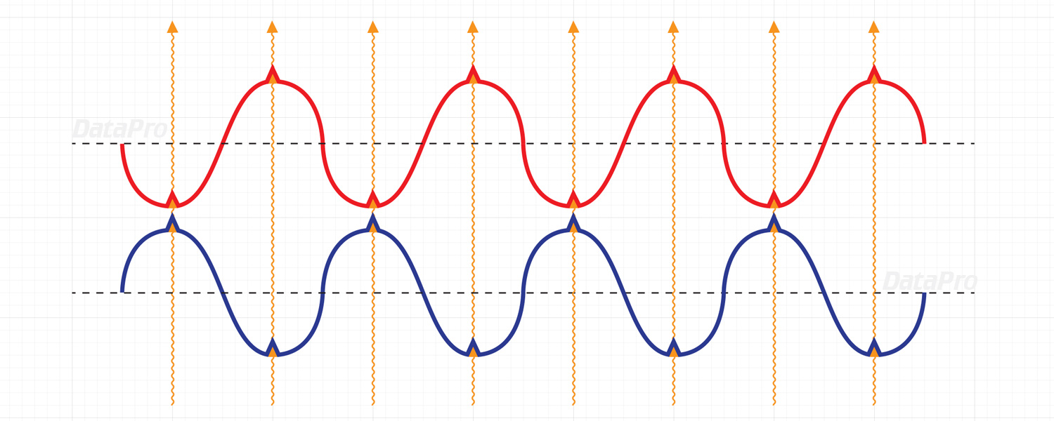
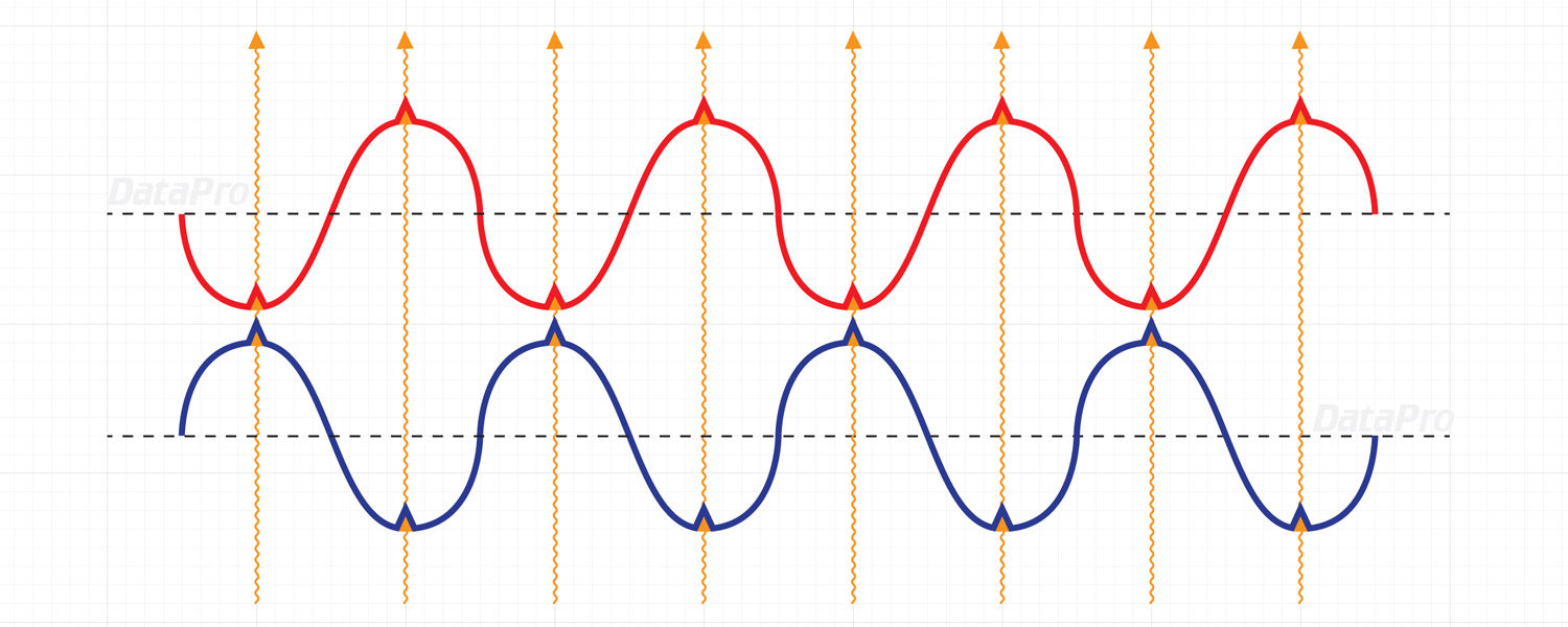
Fig. 1: With a symmetric drive, the two conductors carry opposite signals; the interference (orange) couples equally onto both as a common-mode signal.
2.1. Transformer and electronic balancing
A line can be balanced in two ways, and some common claims (such as the "+6 dB" below) apply only to the electronic case.
Transformer balancing was the traditional professional method. The two conductors are simply the two ends of a transformer winding (an output transformer at the sending end, an input transformer at the receiving end). The signal is the voltage across that winding; there is no separate "inverted" copy and no fixed reference to ground. The winding floats, so only the voltage difference between the two conductors does anything: connecting just one conductor and ground forms no circuit and produces no signal, and at the input only the differential voltage drives current through the winding. This galvanic isolation gives transformers inherently strong common-mode rejection.
Electronic balancing uses op-amp driver and receiver stages instead of transformers. Here the conductors are actively driven and, in most designs, referenced to the device's internal 0 V (they are not floating like a transformer winding, apart from special designs such as those patented by Bill Whitlock). How the signal is split between the conductors affects the level, but not the noise rejection:
- A symmetric (differential) output drives the two conductors with equal and opposite voltages (for example +V on hot and −V on cold). Their difference is 2V, which is 6 dB higher than a single-ended (unbalanced) output running from the same voltage. This is where the frequently quoted "+6 dB" comes from. - An impedance-balanced output places the full signal on one conductor and holds the other at 0 V signal through a matched impedance. The difference is just V, so there is no level increase.
In every case the noise rejection comes from the impedance balance of the two conductors together with a receiver that responds only to their difference (a transformer or a differential amplifier), not from the conductors carrying a "mirror image" of each other. The "+6 dB" and the picture of two oppositely driven signals belong to electronic symmetric drive specifically; they are not a general property of balanced audio.
Applications
Balanced connections are standard in professional audio equipment such as mixing consoles, audio interfaces, microphones, and active studio monitors. The most common connectors for balanced audio are XLR and TRS (Tip-Ring-Sleeve) jacks, shown below.
XLR cable and wiring
XLR connectors are the standard choice for balanced audio. A balanced XLR link uses three conductors, each with a distinct function:
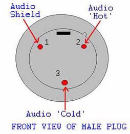
Pin 1 (ground / shield) provides shielding and the ground connection; it carries no signal.
Pin 2 (hot, +) carries the hot leg of the signal.
Pin 3 (cold, −) carries the cold leg of the signal.
This is the AES/IEC standard, commonly summarized as "pin 2 hot." Because the two signal conductors are impedance-matched, interference picked up along the cable appears as a common-mode signal and is rejected by the balanced input at the receiving end. The standardized pinout makes XLR connectors highly reliable and easy to use.
A cable connects the two ends straight through: pin 1 to pin 1, pin 2 to pin 2, pin 3 to pin 3. Note the connector genders: device outputs use a male XLR and device inputs use a female XLR. A cable therefore has a female connector on the end that plugs into an output and a male connector on the end that plugs into an input.
Fig. 2: Front view of a male XLR plug. Pin 1 = shield, pin 2 = hot, pin 3 = cold.
TRS cable and wiring
The TRS cable is easily confused with the TS cable, since both look similar. Their internal structure is different.
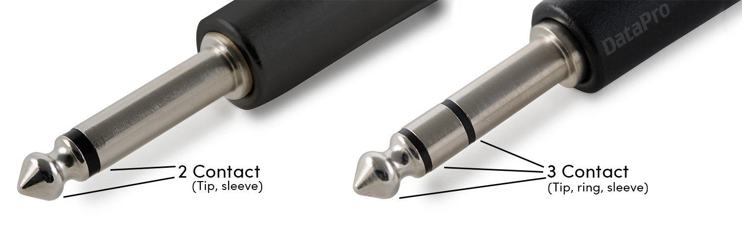
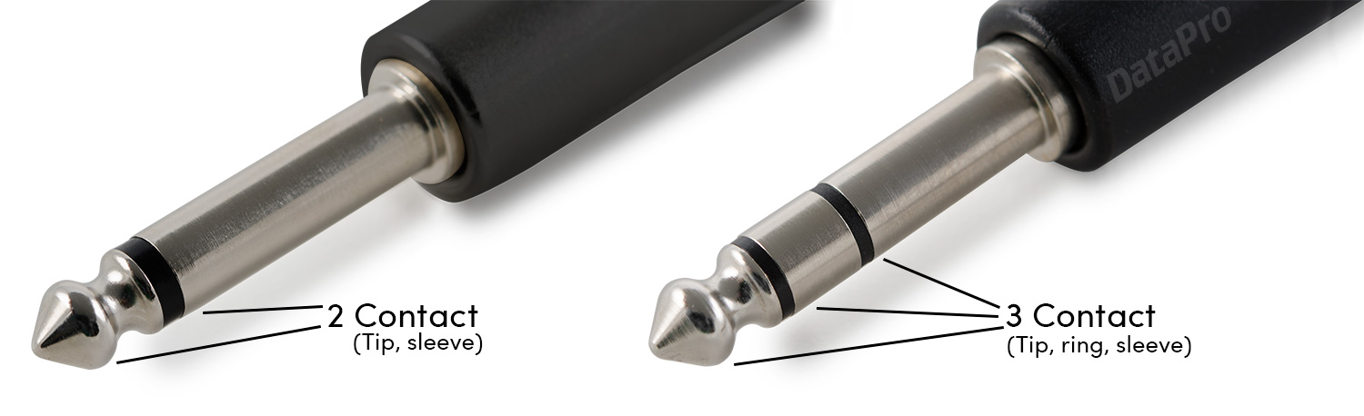
A TS (Tip-Sleeve) connector has two contacts: the tip carries the signal and the sleeve is the ground. A TRS (Tip-Ring-Sleeve) connector has three contacts, which lets it serve two different purposes depending on how it is wired:
Balanced mono: tip = hot (+), ring = cold (−), sleeve = ground.
Unbalanced stereo: tip = left, ring = right, sleeve = common ground.
The same connector is therefore used either for a balanced mono signal or for an unbalanced stereo signal; the device and its labeling tell you which. A plain TS connector, by contrast, can only carry an unbalanced mono signal, so paying attention to the number and function of the contacts is important to avoid signal loss or noise.
Fig. 3: Left: unbalanced TS. Right: balanced TRS.
Advantages of balanced cables
Strong rejection of noise and interference, even over long cable runs.
Cleaner, more reliable signal transfer.
Standard in professional and studio environments.
Balanced vs. Unbalanced
Balanced: two impedance-matched conductors; common-mode noise rejection; XLR or TRS connectors; suitable for long cable runs.
Unbalanced: one signal conductor plus ground; no common-mode rejection, so more susceptible to noise; TS or RCA connectors; best for short cable runs.
Best Practice
Use balanced connections for any run longer than about 3 meters, or in environments with significant electrical interference.
Prefer balanced connections for microphones, active monitors, and any critical signal path in the studio or on stage.
When feeding unbalanced equipment into a balanced input, use a DI (direct injection) box to convert the signal to balanced; a transformer-based DI or a line isolator additionally provides galvanic isolation that breaks ground loops.
To cure hum from a ground loop, use galvanic isolation (a transformer DI or line isolator) or a device's ground-lift switch, which lifts the audio shield, not the mains earth. Never disconnect the protective mains earth to fix a hum.
Check cables and connectors regularly for integrity and shielding.
Avoid running audio cables parallel to power cables to minimize induced interference.
Balanced transmission is very effective at rejecting common-mode noise, but its real-world performance depends on the quality of the cables, the connectors, and how well the two conductors stay impedance-matched across the whole link, which sets the real-world common-mode rejection. Perfect cancellation is rarely achieved in practice, yet balanced systems still offer a large improvement over unbalanced ones. The benefit is not only about cable length; the surrounding environment matters just as much. In electrically noisy settings, for example near lighting dimmers, switching power supplies, or radio transmitters, balanced connections are essential for preserving signal integrity. Conversely, for very short runs in quiet environments, unbalanced connections can be perfectly adequate and are often more cost-effective.
Self, Douglas (Ed.): Audio Engineering Explained, Focal Press, 2009.
Davis, Gary & Jones, Ralph: The Sound Reinforcement Handbook, 2nd ed., Hal Leonard (for Yamaha), 1989.
Whitlock, Bill: "Balanced Lines in Audio Systems: Fact, Fiction, and Transformers," Journal of the Audio Engineering Society, Vol. 43, No. 6, June 1995, pp. 454-464.