This section establishes the relationship between wave propagation at interfaces and the effect of various resonators, which are fundamental both for room acoustics and musical acoustics.
Longitudinal Resonators
In this type of resonator, sound propagation occurs one-dimensionally, i.e., along the direction of the resonator. Two cases are distinguished with different boundary conditions.
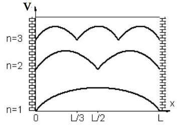
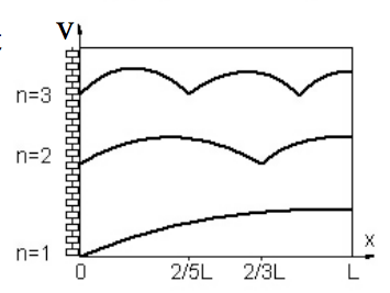
Lambda/2 Resonator
L = n \cdot \frac{\lambda}{2} Where L is the length of the resonator, n is the order or mode, and λ is the wavelength.
This discussion pertains to rigid tubes used as acoustic lines. It considers the fundamental wave, ignoring all losses. It is assumed that the cross-dimensions of the tubes are small compared to the wavelengths being considered, hence no higher wave types occur. The effects presented here are associated with the concepts of reflection, transmission and simple mechanical meanings of short constrictions and short extensions, from which acoustic filters can be constructed using elementary circuit rules. Accordingly, this chapter also provides an introduction to electromechanical equivalent circuits. Furthermore, continuously changing tube cross-sections are dealt with, which are used in funnels and horns, which are used in the construction of musical instruments and loudspeakers.
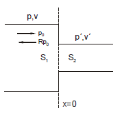
Simple Cross-sectional Jump
At the junction, i.e., at x=0, the pressure on the left must match the pressure on the right.
p_0(1 + R) = p'
p0 is the pressure of the incident wave. For sound velocities, it holds that:
Where v_0 = \frac{p_0}{\rho_0c} and v' = \frac{p'}{\rho_0c} . Introducing the known transmission factor T = \frac{p'}{p_0} , it follows from the above equations that: R = \frac{S_1 - S_2}{S_1 + S_2}
T = 1 + R
Thus,
T = \frac{p'}{p_0} = \frac{2 S_1}{S_1 + S_2}
The "wall impedance" of the cross-sectional jump is: Z = \left(\frac{p}{v}\right)_{x=0} = \rho_0 c \frac{S_1}{S_2}
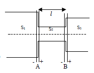
Double Cross-sectional Jump
The drawing below should be viewed from the right side, so we have:
Z \approx \frac{S_1}{ S_2} \rho_0 c\frac{S_2 + j l k S_1}{ j k l S_2 + S_1}
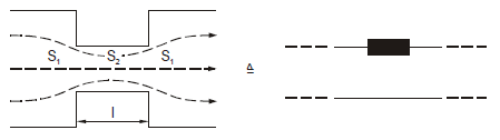
Constriction
For S2<S1:
Constriction For S2≪S1 it follows: Z \approx \rho_0 c + j \omega m'
with m′=\frac{\rho_0l'}{S_1 S_2} l' is not the geometric length of the constriction but includes the "mouth correction":
l' = l + 2 \Delta l
For circular coaxial tubes:
\Delta l \approx 0.8 a
a is the radius of the narrower tube section.
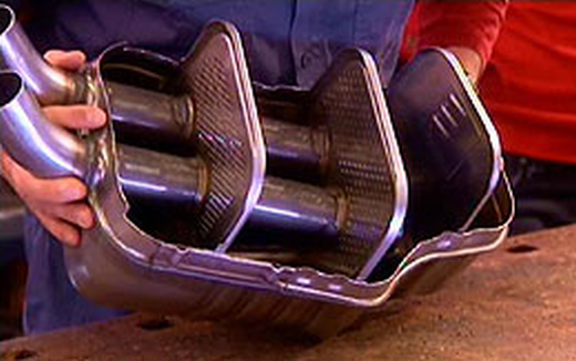
This correction takes into account the fact that the streamlines cannot contract abruptly to the smaller cross-section S2 and then expand again to S1. If a large number of tubes of the type shown above are stacked on top of and next to each other to fill the room, for which the cross-section S1 must be rectangular, and the tube walls, which are ineffective in the first approximation, are omitted, the constrictions remain and form a perforated plate. These are widely used as absorbers for room acoustic design.
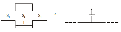
Expansion
For S2≫S1, the impedance has a spring component:
\frac{1}{Z} \approx \frac{1}{\rho_0 c} + j \omega n'
with n′=\frac{l}{\rho_0c^2}\frac{S_2}{S_1}
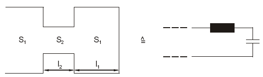
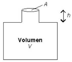
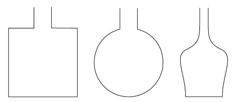
Additionally, the orifice correction must be applied to l_2 . V_1 is the volume of the closed part. Since all dimensions are small compared to the wavelength, its shape is not important. Resonator shapes
A planar Helmholtz resonator is obtained by placing a perforated plate in front of a sound-reflecting wall. (Important in room acoustics!)
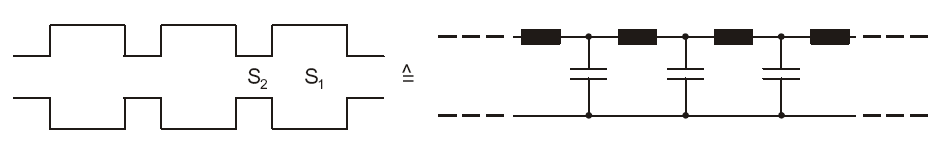
A succession of pipe expansions and constrictions results in an acoustic low-pass filter: Resonator series circuit Its cut-off frequency is
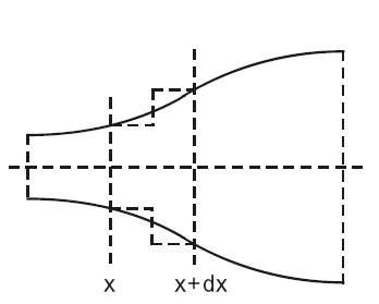
Imagine removing a very small segment of length dx from the pipe, so the cross-sectional change dS can be considered concentrated at a jump. Continuous Cross-Sectional Change
This does not change the force ratios, so they still apply: -\frac{\partial p}{\partial x} = \rho_0 \frac{\partial v}{\partial t}
And hence, the solution for the pressure in the funnel is:
p(x, t) = \frac{C}{x} e^{j(\omega t - kx)}
with the initially undefined constant C.
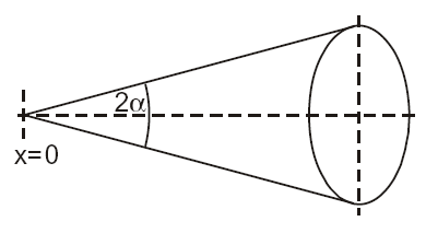
Accordingly, a spherical wave propagates in the funnel. If there is a sound source of volume rapid amplitude Q in the vicinity of x=0, it is not distributed over the entire solid angle 4π as with free propagation of a spherical wave, but only over the solid angle enclosed by the funnel \Omega = 2\pi (1 - \cos \alpha) \quad \text{with} \quad \alpha = \arctan\left(\sqrt{\frac{b}{\pi}}\right)
If this formula is compared with the formula for the spherical shaft, the value for the constant C is obtained:
C = \frac{j\omega\rho_0\hat{Q}}{\Omega}
A comparison of the equations shows that the funnel increases the intensity by a factor of (4π/Ω)2 and the total power by 4π/Ω compared to free spherical wave propagation. This is the basis for the "sound amplifying" effect of the funnel.
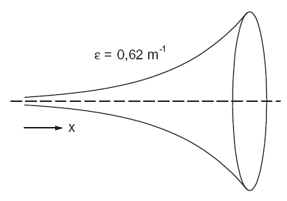
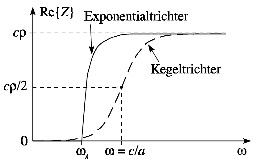
Below the circular frequency \omega_g , no wave propagation is possible; above it, the propagation speed is frequency-dependent, exhibiting dispersion:
W_s = Re \{ Z_m \} = S_0\rho_0c\sqrt{1-\left(\frac{\omega_g}{\omega}\right)^2}
is the effective radiation resistance.
For ω≫ωg, it roughly corresponds to the radiation resistance for a sound source in a sound-hard pipe of cross-section S0. It disappears for ω<ωg. Above its cut-off frequency, the funnel therefore causes a significant increase in the radiation resistance and thus the radiated power. Strictly speaking, all the results in this section only apply to infinitely long funnels, but also approximately to funnels of finite length.